
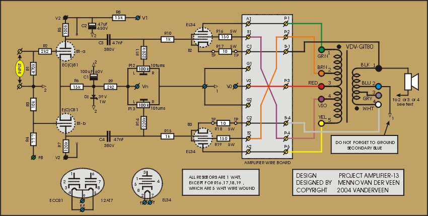
Inside amplifier 13 we find a strange combination of negative and positive feedback. The cathodes are connected to the secondary winding. This delivers negative feedback. The amplification factor lowers, the distortion is suppressed and the damping factor gets larger. However, the screen grids are connected inverse to their UL-taps on the primary, which is positive feedback. This combination of negative and positive feedback gives very interesting results, they will be discussed following. Click ![]() here to download the measurement results. Click the circuit diagram for full page view.
here to download the measurement results. Click the circuit diagram for full page view.
The sound character of amplifier13 is not optimal, it is tiring, harsh, fatiguing for the ears. It might be useful for guitar overdrive, but even that would not be my preference. Why then do I pay attention to such a not optimal sounding amplifier? Well, even from the bad you can learn, and this certainly is the case here.
Amplifier 11 has taught us that screen grid negative feedback lowers the open loop amplification by a factor 1/6. Now the feedback is reversed, it is positive feedback. This will raise the amplification by the inverse of 1/6, which is a factor of 6. The Ia-Vak-Vgk characteristics will blow up in all directions, especially to the left side, resulting in more output power. This larger power was the initial goal of this type of amplifier. That is why I gave it the name “Super Pentode” (see *1). If we would only apply the positive screen grid feedback, then the amplifier would be unstable and a perfect oscillator. However, there is extra the negative feedback at the cathodes. This makes the amplifier stable again. The amount of negative feedback at the cathodes is given by Ns / Np = 1 / 22.4 = 0.045. The total effective amplification is the original B2 and B3 amplification of 190 times the two factors mentioned: 190 x 6 x 0.045 = 51.3 (see A-unload = 46.6 measured). The precision of this calculation can be improved (see *2). However, this simple approach delivers enough first insight.
The measurements in form-13.doc show two special results. Firstly, the output power has got less compared to the power in amplifier 10. See *3, where it is explained in detail that there should have been more negative cathode feedback for improved output power. Secondly, there is the strange effect that the –3dB highest frequency has raised. This is caused by the leakage inductance between the primary and secondary windings of the OPT. The leakage creates a phase shift between the anode and cathode voltages, resulting in less negative cathode feedback at higher frequencies. This explains as well the harsh sound character of the amplifier. Less negative feedback at higher frequencies results in less suppression of the distortion at higher frequencies.
As I said, this amplifier does not sound optimal. But is gives us a good insight what happens when positive and negative feedback are combined and its effect on the character of the sound.
Next time: amplifier 14
*1: Menno van der Veen: “Moderne High-End Buizenversterkers met ringkern-uitgangstransformatoren”; hoofdstuk 8; ISBN 90-5381-089-7
*3: Pierre Touzelet, Menno van der Veen: “Small signal analysis for generalized push-pull tube amplifier topology; 112th AES Convention, Munich 2002; paper 5587