
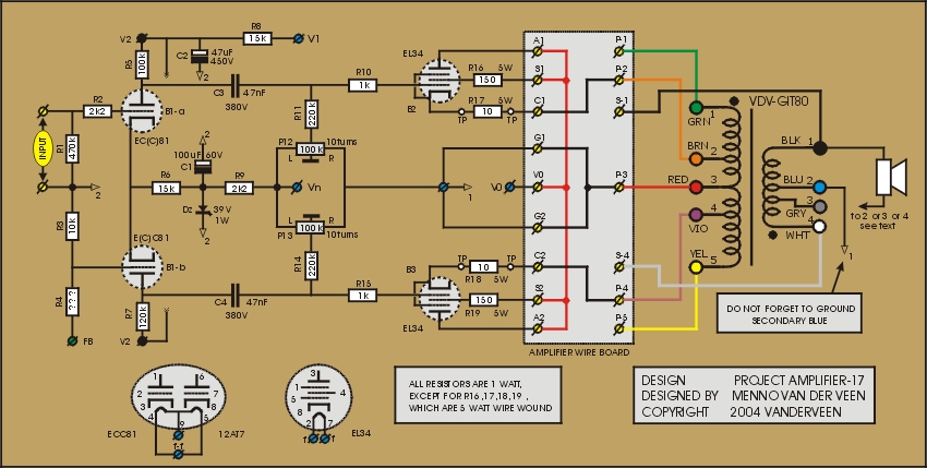
In amplifier 17 again the screen grids are connected to their anodes. This means that half of the output power of the power tubes is available. The cathodes are connected to the primary taps 2 and 4. The primary center tap is to ground. The driving tube B1 has an almost impossible task in this concept. It hardly can drive the power tubes and therefore the output power is limited to a mere 8 Watt. Click ![]() here to download the measurement results.
here to download the measurement results.
The sound character of amplifier17 is clean and open and detailed. The bass reproduction is powerful and controlled. This is caused by the large damping factor.
The frequency range is wide because the power tubes drive the OPT with their low output impedance. Also the Miller capacitance at the control grids plays no role anymore, while the anode and screen grid are at the constant supply voltage.
To find the optimal load impedance Zcc for this special amplifier, a simple set of measurements was performed. The output was connected to a variable dummy load Zs. For every resistance setting the maximum output voltage Vs was measured. The output power is maximum when Vs2/Zs is maximal. This appeared to be the case for Zs = 4 Ohm, which is equivalent to Zcc = 900 Ohm between the primary taps 2 and 4.
In this amplifier the driving tube B1 has a difficult life. This can be explained as follows. At an output power of 8 Watt, the alternating voltage between the primary taps 2 and 4 equals 85 Vrms. The cathode of each power tube swings with 42 Vrms. The amplitude of each cathode alternating voltage equals 59 V. Above this large voltage, the control grid of the power tube needs an extra alternating voltage of almost 30 V. This means that each halve of the driving tube B1 must deliver an AC voltage of almost 59 + 30 = 89 V amplitude. This is the limit of what tube B1 can perform. This explains why we do not get the full expected power of 14 Watt. You can expand the driving voltage by using bootstrapping around B1. However, I leave this to the DIY-er for further exploration.
It is easy now to calculate the actual output impedance of the power tubes. This equals the measured secondary output impedance of 1.5 Ohm times 900 / 4 = 338 Ohm. So, each tube behaves now as a voltage source with a resistance of 169 Ohm in series.
Amplifier 17 has the full potency to become a magnificent high end amplifier. Only the circuit around B1 needs further attention and improvement. I do not prefer this circuit for guitar amp use; it simply sounds too clean.
Next time: amplifier 18