
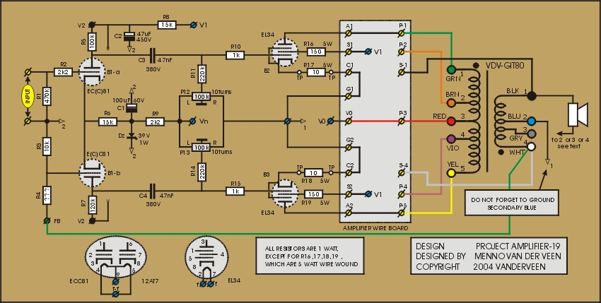
The power tubes B2 and B3 can deliver twice the output power by raising the supply voltage from 360 V to 740 V and using a primary impedance Zaa = 8 kOhm. By doing so, the alternating current through the tubes stays as it was, while the alternating voltage doubles. The screen grids can't handle 740 V; they should stay at 360 V. See the schematics below and the specifications (click ![]() here) for this 78 Watt output power amplifier.
here) for this 78 Watt output power amplifier.
There are several ways to explain why you get such a large output power in this amplifier. I now use the Ia-Vak-Vgk characteristics as a tool of explanation. How strange this may sound, in amplifier 19 these characteristics have not changed compared to amplifier 10. This is because Vg2 is equal to 360 V in both amplifiers. The quiescent point of amplifier 19 is at 740 V, meaning that the maximum voltage swing has doubled. The load line (Zaa) should be less steep compared to amplifier 10 (from 4 kOhm to 8 kOhm), because the tubes can not deliver twice the maximum current. The output power equals the alternating voltage squared, divided by the primary impedance Zaa. Using the numbers given, it is clear that we get at least twice the output power compared to amplifier 10. In practice we get even more.
Especially now it is important to pay attention to the quiescent current through the EL34 power tubes. Their anode dissipation equals 25 Watt maximum, meaning a maximum quiescent current of Io = 25/740 = 34 mA. With this value the life span of the tubes will be short and therefore Io = 25 mA will be a wiser choice. However, this quiescent current is too small in amplifier 19. When studying the Lissajoux presentation of Vout (Y-axis) versus Vin (X-axis) at the oscilloscope screen, a clear transition of class A to class AB is visible. The Lissajoux picture should show a straight line, and this is certainly not the case. This means severe third harmonic distortion at higher output levels, and only a larger quiescent current Io can cure that.
Therefore I advise to use different power tubes in this amplifier. A much better choice is the 6550 with quiescent current at 40 mA (Pa,max = 35 Watt). The best choice is the EL156 or KT90 or KT99. These tubes have a maximum anode dissipation of 50 Watt, and they easily can handle a quiescent current of 50 mA. I tested with EL156 tubes and the third harmonic distortion visibly disappeared in the Lissajoux measurement, with a nice straight line as result. Also the listening test revealed absence of harmonic distortion when EL156 tubes were used.
The power tubes are in pentode mode, and therefore the damping factor is very small. This can be improved by applying overall negative feedback with R4. In the schematics the value of R4 is indicated by "???", while the bottom side of R4 should be connected to the secondary pin 4 (white). First listen without R4, then give R4 the value 1 MOhm, and continue making R4 smaller, up till you notice that the damping is large enough for good bass control. You can do this by ear. You also will notice that enlarging the feedback (smaller value of R4), makes the amplifier less dynamic. As always: feedback is a matter of win and loose, and that's why I advise that the trimming of R4 should be by ear. Let your ear decide for the best balance between all goodies of this amplifier.
The measurements show another peculiar item: the lowest full power frequency is at 24 Hz. In earlier publications I told about my design goal of 80 Watt at 40 Hz for the VDV-GIT80 transformer core. Did I make a mistake in my transformer design? No, I didn't. These good low frequency results only show that I am continuously improving the VDV-GIT80 transformer. Especially a new high quality core steel is responsible for this fine result.
Next time: amplifier 20 with brute power and local feedback.