
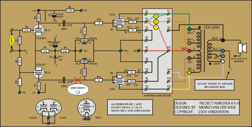
In the amplifiers 4-5-6 the tube B3 is changed into a pentode mode 50 mA constant current source. This compensates the quiescent current of B2. The OPT is no longer in saturation. Only the right side wire of C4 should be disconnected to change B3 into a constant current source. Now we can investigate how real SE amplifiers should sound. See the schematics for all the details and click ![]() here to download the specifications.
here to download the specifications.
The impact of B3 as a current source is fantastic. The core of the OPT is not saturated and as a result the bass is powerful, strong and dynamic. The typical silky sound character of Single Ended is absolutely clear and present. My ears love this and to be honest, I don't care at all about distortion. This is how amps should sound. I am thrilled, but at the same time, it is not yet optimal. There must be reasons for improvement. Some details are not totally clear and following I will discuss what is going on.
Firstly, it is remarkable that all three amplifiers have the same 5 Watt output power. I expected amplifier 4 to have more power (close to 10 Watt). It seems as if B3 is eating power, as if B3 is not an optimal current source. This is the case: B3 is in pentode mode and its plate resistance is not infinitive. So, I should change something around B3 to make its plate resistance larger. The easiest way to do so, is to give B3 its own cathode resistor (470 Ohm 2 Watt) and to trim the quiescent current with P13 again to 50 mA. Now the plate resistance of B3 will be close to 100kOhm which is large enough for this application. I leave it up to you to implement this improvement.
There is a second reason why these amps are not yet optimal: they hum. Although the quiescent currents of B2 and B3 are equal, there effective plate resistances are unequal. Therefore the ripple voltage on the supply voltage Vo is not fully compensated. To improve this, the supply voltage should have less ripple. When we add a 10 H choke after Vo plus an extra buffer capacitor of 100uF/450V, this issue is solved.
The third reason for improvement is found in the EL34. Its quiescent current is set at 50 mA at 370 V supply and 2kOhm primary load. This operating point is not optimal. It was selected as the same operating point for all the amplifiers in this project. A much better choice is 60 mA quiescent at 5 kOhm primary load. Because the OPT is universal, all these changes can be easily implemented. In amps 19 and 20 I advised to use 6550 and EL156 for B2 and B3. Also here these tubes are much better, because they allow for larger quiescent current settings (max 135 mA with the EL156). They will give larger output power and lower distortion. Again I leave this up to you to research.
The next time I go one step further. What will be the influence of cathode feedback in single ended amplifiers? This truly will lower the plate resistance of B2. This effect should be clear ....
Next time: SE amplifiers 7 to 9 with cathode feedback