
The students of the TubeSociety academy design and construct each year their own masterpiece. In 2006 they decided to make an all valve preamp with moving coil or moving magnet input, a line stage, a balanced active input stage, completed with a headphones amplifier and a buffered recorder output stage. Really a hard task where 9 students combined all their skills into one product, constructed by the youngest of them (because he had to learn a little bit). There was no time for a decent PCB design, the amp was built hard wired. To exclude hum the power supply was in a separate case.
Introduction
The students of TubeSociety academy in The Netherlands follow a one year intensive training in valve electronics.
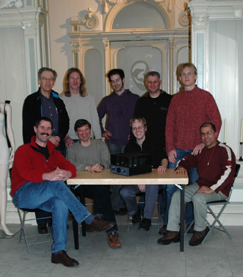
picture 1: TubeSociety students
The first quarter is focuses on pre amplification, the second on power amps, the third deals with power and audio transformers, while the last is about how to measure and the evaluation of the masterpieces they constructed.
click for more detail
figure 1: functional diagram of the TS-VV-2006 pre amplifier
In the year 2006 the complete valve pre amp (the concept is shown in figure 1) was divided into small parts where two or three students worked together.
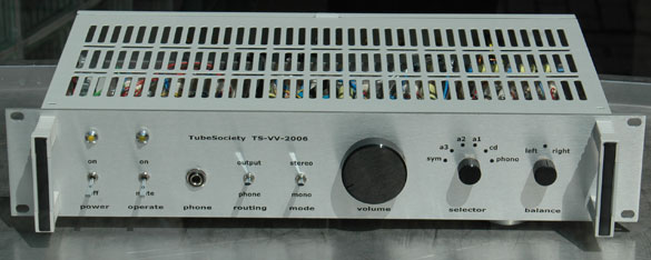
picture 2: TS-VV-2006 front side
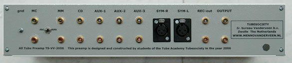
picture 3: TS-VV-2006 back side
The pictures 2 and 3 show the result of their hard labor. A 19" 2 HU case is used, delivered by 2). The front is screened with a plastic sheet with black lettering designed in CorelDraw and fabricated by 3).
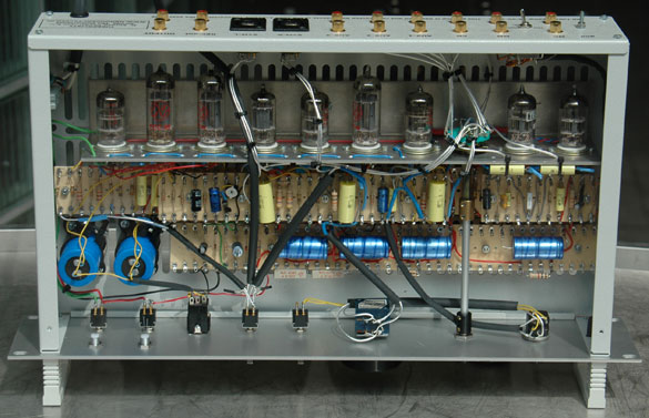
picture 4: TS-VV-2006 internal
Picture 4 gives a good impression of the inner construction. All valves are on a sub chassis (as in the old Revox G36 recorder), while the resistors and capacitors are placed on boards.
picture 5: filament supply wires at the tube side of the sub chassis
Picture 5 shows a smart detail of the construction. First the filament wiring is placed on the sub chassis, on the other side of the components, to prevent any hum from the 6,3 V alternating filament supply. All valves used are good available and their noval pinning is equal. Only the filament pins differ, however that will be discussed when we deal with the power supply. See 4) about all the technical specifications of the valves used.
click to enlarge
figure 2: Pin numbering of the valves
The MC-MD pre amp stage
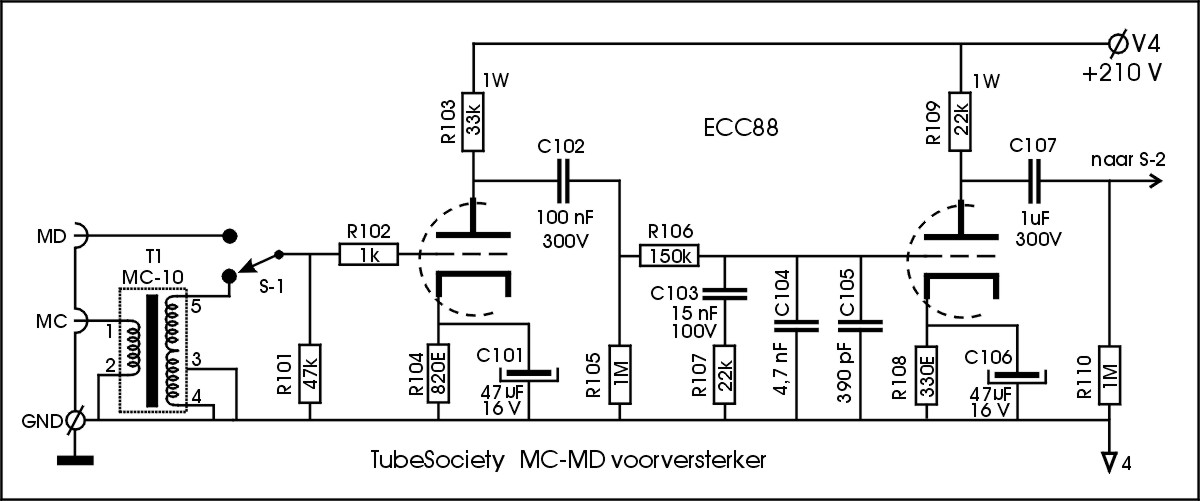
Figure 3 shows the schematics of the turn table pre amp.
click for more detail
figure 3: MC-MD pre amplifier
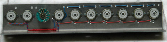
The moving coil input uses the MC-10 step up transformer which amplifies 10 times; see 5) for more details about this special transformer. With the selector switch S1 the moving magnet signal can be fed into the pre amp stage directly. Picture 6 shows how this section is wired, directly between the MC and MD input sockets.
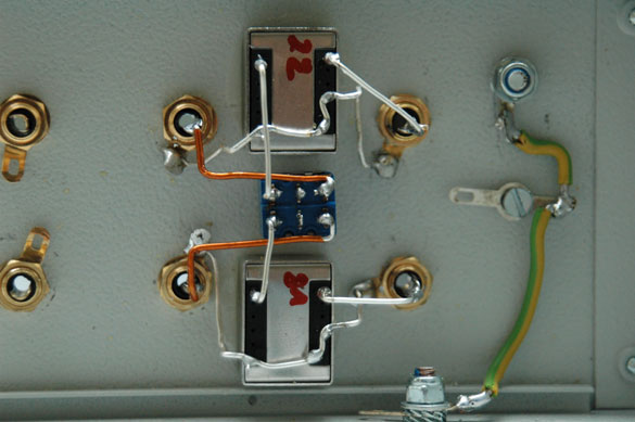
picture 6: the MC-10 step up transformer with switch S-1 placed directly
The moving magnet input has the standard R101 = 47kOhm input impedance. Often one applies a 100pF capacitor in parallel with R101, but listening experiments showed a higher sound quality without this capacitor. See 6) for a profound discussion about this remarkable effect. Resistor R102 damps any oscillation of the first section of the ECC88. After the amplification of this first section, a passive filter section creates the RIAA correction curve. Especially 7) gives the complete theory and formulas how to calculate this filter. When these calculations are followed, please take into account the effective output impedance of the first tube section, which is in series with R106. With good reasoning the capacitors C101 and C106 are placed parallel to the cathode resistors, to ensure that each tube section has the lowest output impedance possible. Also the amplification is now maximum and only little less than µ = 33. The star grounding of this preamp section is indicated with the number 4. See the power supply section later on for more information about smart grounding.
The effective amplification of the MD pre amp equals 57,5 times at 1 kHz. The standard signal level at C107 is set by design at 250 mV, which means that the input sensitivity of this pre amp equals 4,3 mV, which is a good level.
In 6) a precise anti RIAA circuit is proposed, which was used to determine any deviation from the correct RIAA curve. The maximum deviation in the left channel was 0,2 dB while in the right channel 0,6 dB was found, caused by the capacitors C103,104,105 being 10% types.
The -3dB frequency range starts at 20 Hz, which is a good value to prevent excessive amplification of rumble. The high -3dB frequency lays at 60 kHz, which indeed is impressive.
Also impressive is the abundant headroom; 45 dB at 20 Hz, 44 dB at 1 kHz and 33 dB at 20 kHz. These good numbers show that any clicks on the record will be handled well without overdriving the pre amp.
The current drawn by the complete pre amp section per channel equals 11,5 mA. The working point of the tubes is selected such that they operate in the most linear part of their characteristics. The final section of this article will deal with how this pre amp section sounds.
Balanced input
Nowadays often balanced in and outputs are used on CD players and mixing consoles. To connect the preamp to such outputs a special balanced circuit is developed and shown in figure 4.
click to enlarge figure 4: Active symmetrical amplifier
An ECC82 is used as a differential amplifier where the two cathodes are connected to each other. The transistor TR201 functions as a current source to ensure a high impedance at the connected cathodes. The current of this source is given by 6,8 V over the special low noise zener diode Z202 minus 0,6 V between the basis and emitter of TR202, divided by R208 = 470 Ohm, and equals 13,2 mA. The trim pot P201 enables exactly equal currents of 6,6 mA through both valve halves. These equal currents are essential for the highest CMRR (common mode rejection ratio).
Professional mixing consoles can have output levels up to 20 dBV or even more. In order to prevent any overload at the inputs of the differential amplifier, the control grids are lifted to a voltage of 24 V. Even an unbalanced source can not overdrive the input under this condition.
The effective amplification of the circuit equals 1,5. The output is taken of one of the two anodes and fed through C205 to the line stage of the pre amp. The numbers given by the inputs equal the pin numbering of an XLR socket.
The most important features of this circuit are: -3dB frequency range from 16 Hz to way beyond 100 kHz; CMRR better than 60 dB and constant for frequencies between 20 Hz and 20 kHz. The input impedance equals 100 kOhm per phase, while the maximum output voltage is +19 dBV. This is little less than the +20 dBV mentioned earlier, however, who can hear a headroom difference of 1 dB? How does this circuit sound? See the final chapter of this description.
Recorder buffer
All the inputs of the pre amp are fed to the input selector switch S-2. The selector output is connected to the buffer circuit shown in figure 5.
click to enlarge
figure 5: Recorder buffer
The output of this circuit goes to the input of a recorder. Whatever recorder is used, broken or working, or even with asymmetrical distortion at its input, all these nasty things will have no influence on the purity of the audio signal in the pre amp. The buffer circuit creates a complete separation between its input and output.
There is no need for any amplification in the buffer circuit; the only demands are separation and lowest output impedance to allow long length of coaxial interlinks. A standard cathode follower meets all the demands. The -3dB frequency range starts at 15 Hz and goes up to 1,5 MHz when the output of the buffer is loaded by a 10 kOhm impedance. The quiescent current of the circuit equals 4,55 mA per channel; the effective output impedance is 350 Ohm and the amplification equals 1.
Line stage
After the input selector S-2 the selected audio signal goes through the balance and volume pots to the line stage as shown in figure 6.
click to enlarge
figure 6: Line amplifier
Its effective amplification factor equals 4 times. We designed for a nominal output signal level of 1 Vrms. This means that the input level of the line stage equals 250 mVrms, as mentioned before. An ECC99 is an excellent choice for a valve at this place because of its low output impedance and good amplification factor. By placing a capacitor over the cathode resistor R403, it is guaranteed that the output impedance stays small and equals the plate resistance of the ECC99 at the operation point in parallel with the anode resistor R403. With the little negative feedback through R401 and R406 the effective amplification is well controlled and also the output impedance is extra smaller. This feature is important when long interlinks are connected to the output of the line stage. Their inherent capacity of 100 pF/m might limit the high frequency range when the output impedance would be too large.
The input impedance of the line stage is 50 kOhm when the volume pot P402 is at its maximum setting. The balance pot P401 has a range of 3,5 dB per channel (in total a range of 7 dB between left and right). This seems a little range but the function of this balance pot is to only cope with small differences in amplification factors. The MD stage functions in open loop with no internal feedback. Therefore small differences in amplification of the valves used might cause a little unbalance. With the range of P401 you always can ensure that the "voice in the middle" will be heard exactly in the middle of the sound stage.
The -3dB frequency range of the line stage starts at 5 Hz and goes up to 55 kHz. This might look not so wide, but it is wide enough. The 55 kHz is caused by the Miller capacitance of the ECC99 in parallel with the feedback resistor R406. Per channel a current is drawn of 15 mA while the output impedance equals 500 Ohm. The maximum output level in a load of 10 kOhm with low distortion is 28 Vrms = 29 dBV.
Headphones amplifier
This amplifier applies an ECC99 in the well known White Cathode follower circuit (see 8)), although others mention it to be an OTL circuit (see 9)).
click to enlarge
figure 7: Headphones amplifier
The most important features of this special circuit are that it can handle complex capacitive loads very well and its small output impedance. The rise and fall times of square waves are made equal with the feedback through C503 and R508.
The demands on this circuit are heavy because most headphones nowadays have a low impedance of 32 Ohm, in stead of the older friendlier impedances around 160 or 600 Ohm. Compare this 32 Ohm to the output impedance of 500 Ohm of the line stage, and one will understand that valves will have a difficult task to drive such small impedances.
The ECC82 in front of the ECC99 is used as pre amplifier driver stage and the total amplification is set at 2 times through the resistors R501 and R510. When the output is loaded with 32 Ohm, the -3dB frequency range starts at 6 Hz up to 180 kHz. The maximum output voltage in 32 Ohm is 2,1 Vrms. This looks almost like nothing, but compare this specification with the sensitivity of 114 dB-SPL per Vrms of the Sennheiser PMX100 headphones. Then the maximum sound pressure level will be equal to 114 + 20.log[2,1/1] = 120 dB-SPL. This surely is loud enough to damage your ears.
As said older headphones have larger impedances and this circuit can drive them very well, with higher output levels than the 2,1 Vrms mentioned earlier. The output impedance of the circuit is 14 Ohm and this is good enough for a decent damping of the headphones membranes. Some headphones like a larger output impedance, which can be constructed by placing an extra resistor in series with the output capacitor C504.
The power supply
The power supply is split into two parts. An external case with the power transformer and the first rectification and buffering; see figure 8.
click for more detail
figure 8: Power supply in external case
The second part of the supply is inside the pre amp and shown in figure 9. In a sensitive pre amp, like this design, it surely is wise to place the power transformer external. Then its magnetic stray fields can not enter the sensitive electronics and the mu-metal shielded MC-10 step up transformer. This absence of stray fields also gives you more freedom to place the grounding points and the coaxial cables.
click for more detail
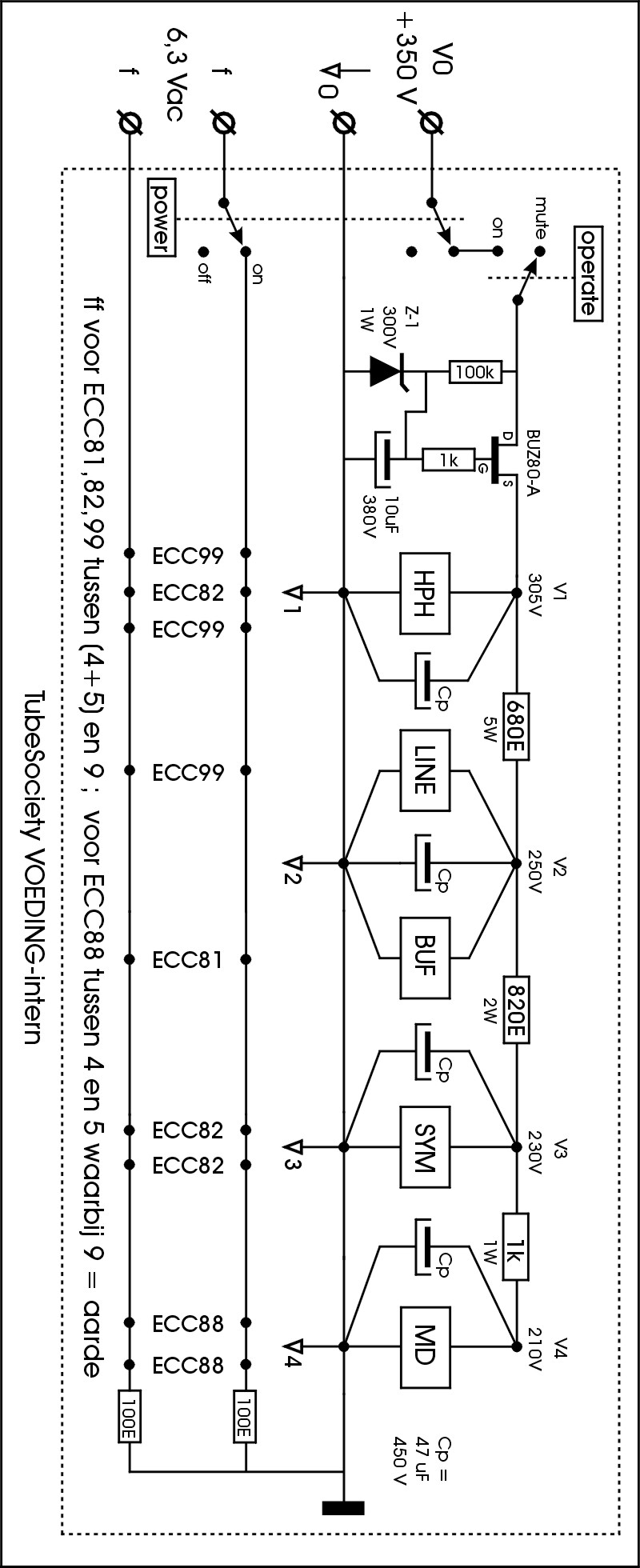
figure 9: Internal power supply schematics
The power transformer is the well known VDV-POW80, see 10) for more details. This transformer even has an extra high voltage winding which is not used in this application. One might consider to use this winding for a complete separated supply for the right and for the left channels. However, such nice actions are left to the DIY-er.
The high voltage is rectified and buffered with 330 µF with a 100 kOhm resistor in parallel. The filament voltage and high voltage is connected to a Speakon socket at the external supply case. The preamp has a four wire very good shielded supply cable connected to a Speakon plug that fits into this socket.
The power switch in the pre amp switches the filament voltage as well as the high voltage. The "operate" switch switches only the high voltage, which enables "muting" of the pre amp.
The Mosfet BUZ80-A with its components functions as an excellent choke and creates a slow start up (0,5 sec) of the high voltage. This is an essential feature because this will prevent the burning of the contacts inside the switches. The "choke" is followed by standard R-C networks for buffering and supply of the different functional blocks inside the pre amp.
The different grounding points are also visible in figure 9. Each numbered grounding point is a floating star point close to the valves of each block. These separated star point really prevent large audio currents of for instance the headphones amplifier to enter the sensitive circuits like the turn table pre amp section. Only star ground point 4 is connected to the metal casing. This type of grounding prevents any audio currents to run through the metal of the case, for the simple reason that the metal of the case is no high quality audio wire metal.
Figure 9 shows that the filament voltage is fed to all valves in parallel, and the filament pin numbering of each valve is indicated. Two 100 Ohm resistors are used to ground the filament to prevent any filament hum.
How to construct and listening impressions
All resistors in the pre amp are carbon resistors; they sound the best in our opinion. All the internal audio cables, inclusive the grounding cables, are silver wire (Siltech and Ketelaar). The switches can be bought at 2) while the valves and their sockets can be ordered at 11) or any other decent shop. The Alps volume pots and component boards are sold by 12).
After completion of this pre amp you surely need some warming up days for a good sound quality of this amp. Then the sound character will be very dynamic and open. You can hear very well that the line stage draws a lot of current and functions deep in class A. The soundstage is very stable, even under excessive dynamic conditions. The MC-MD pre amp sounds warm with a lot of open space, no hiss is heard and you clearly can notice the large headroom because clicks and pops do not overdrive this section.
The Mullard ECC88 is an optimal choice for the valves of the turn table pre amplifier. The reorder buffer does not sound at all, as it should. The symmetrical input amplifier is very quiet and its character is smooth, caused by the absence of any distorted signals. Listening with the headphones really is a pleasure, no noise at all and a very open detailed deep soundstage.
Literature and where to find information:
1: www.mennovanderveen.nl / tubesociety
2: www.farnellinone.nl
3: www.dekleine.nl
4: www.duncanamps.com
5: www.mennovanderveen.nl / transformers
6: www.WaltJung.org : Lipshitz & Jung: "A high accuracy inverse RIAA network"
7: Stanley P. Lipshitz: “On RIAA Equalization Networks *1”; JAES 1979 June, pp.458-481.
8: H. de Waard: "Electronica", hoofdstuk 5.7
9: www.headwize.com / projects
10: www.mennovanderveen.nl / project number 9
11: www.amplimo.nl
12: www.business.conrad.nl
13: for any questions: