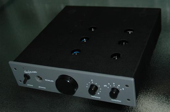
This modification of the Vanderveen MCML05 pre amplifier is totally for free. You have to buy the few components yourself, there is no PCB, it is very simple and I totally leave the implementation to you.
Why?
My pre-amp has a recorder output for a recorder or a mixing desk. The output is taken from the selector S-3 via a 1kOhm (R41) resistor, see figure 1.
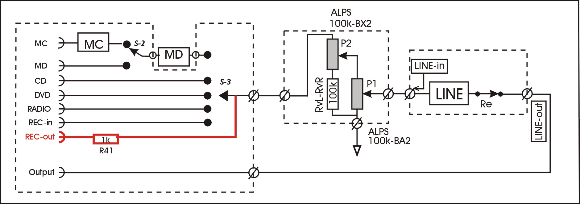
figure 1: recorder output (in red)
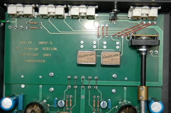
photo-2: the situation before modification
This solution is very simple and is based on the high input impedance (environment of 100 kOhm) of most recorders. This impedance will hardly load the signal sources like a CD player and a tuner that are connected to the MCML05 inputs. However, I noticed a severe loading under special circumstances, largely distorting the sound. The new buffer is designed to prevent this situation.
Modern recording equipment and mixing desks use integrated circuits nowadays. They do not load the recorder output as long as the recording equipment is switched on. However, when the equipment is switched off, a nasty effect occurs. The IC-inputs are protected by means of diodes to the positive (Vcc) and negative (Vss) supply rails. In switched off condition, Vcc and Vss equal 0 Volt, and then the protecting diodes effectively load the signal source. Figures 2 and 3 clearly show what happens; the diodes create severe distortion.
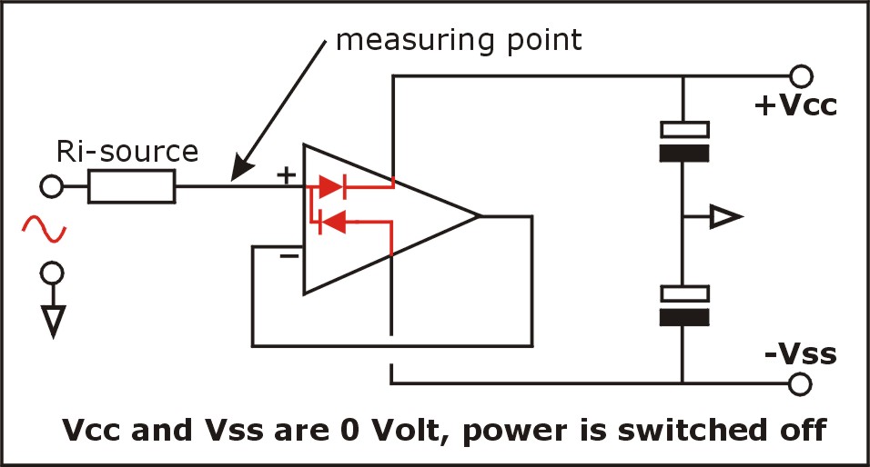
figure 2: protecting diodes limit the input signal
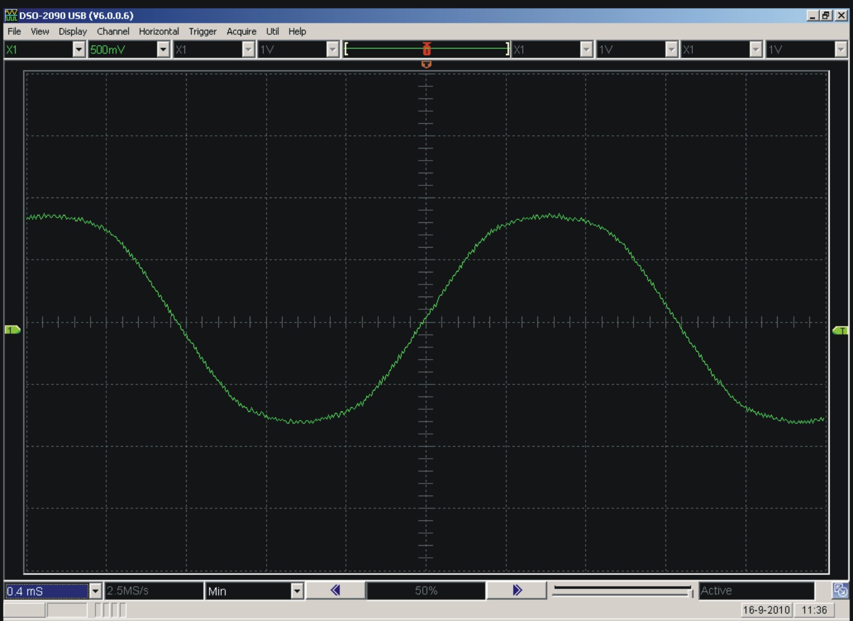
figure 3: measured limiting of the input sinus;
frequency = 400 Hz; vertical = 0,5 V/div.
In my studio, I always disconnected the recorder output to my mixing desk when the deck was switched off. But one day I forgot to do that, with the final result that my client did not like the sound of my amps at all! I lost this client and such a nasty situation should never happen again. That's why I decided to design a buffer circuit that totally separates the recorder output from the input selector. In this article I discuss this buffer circuit.
Specifications
The new buffer circuit should have the following specifications: no capacitors because you can hear them. The distortion and hum and hiss should be negligible. The frequency range should easily be over 100 kHz and the output voltage headroom should be 20 dBV. The input impedance should be large because the buffer may not load the signal sources. Also the output impedance should be low allowing long interlinks without degrading the frequency range. If the buffer output is shortcut, then nothing should be noticed at the input of the buffer and large shortcut currents may not occur. The power supply of the buffer may not send supply currents through the ground traces at the PCB, while they are only meant for audio signal currents. The buffer should be simple to implement on the existing PCB's inside the MCML05 without any change in these PCB's. The power demand of the buffer should be negligible and the buffer circuit should not react on the output impedances of the signal sources. Especially this last demand appeared to be a tricky one.
I tested several solutions for this buffer, like a FET source follower, but I found too much distortion. A valve cathode follower could work, but the filament current demand was too large for the power supply, and it sounded too "technical". The follower also asks for coupling capacitors, which I did not wish to use. So, these solutions were no good.
I decided to use an integrated circuit, then I could meet all the conditions. I selected the OPA2134, which is much better than the standard TL072. However, Douglas Self indicated in his fantastic new book "Small Signal Audio Design" that I might have used the NE5534 as the best solution. I totally believe him, but I had OPA in stock and NE out of stock. By the way, this book of Douglas is of high interest and importance. I advice to buy it, very good and reliable and valuable information!
The buffer circuit
The final solution is shown in figure 4, while figure 5 shows how you can construct it on a small experimental PCB. Figure 6 shows the connections to the input PCB and figure 7 shows how to connect the Vcc and Vss supply wires. The photo gives additional information about how I implemented the buffer.
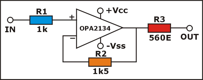
figure 4: the new buffer (1 channel shown)
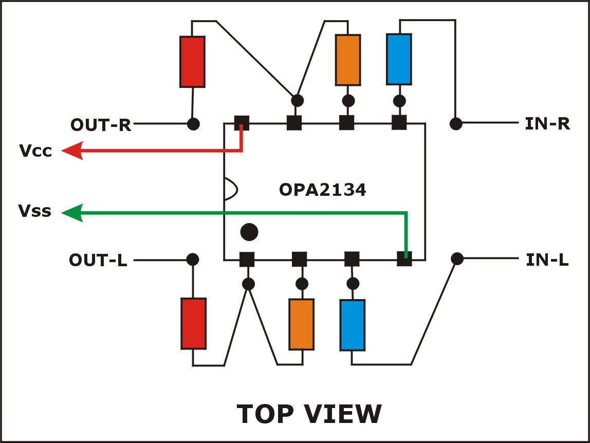
figure 5: how to construct the circuit (stereo-version)
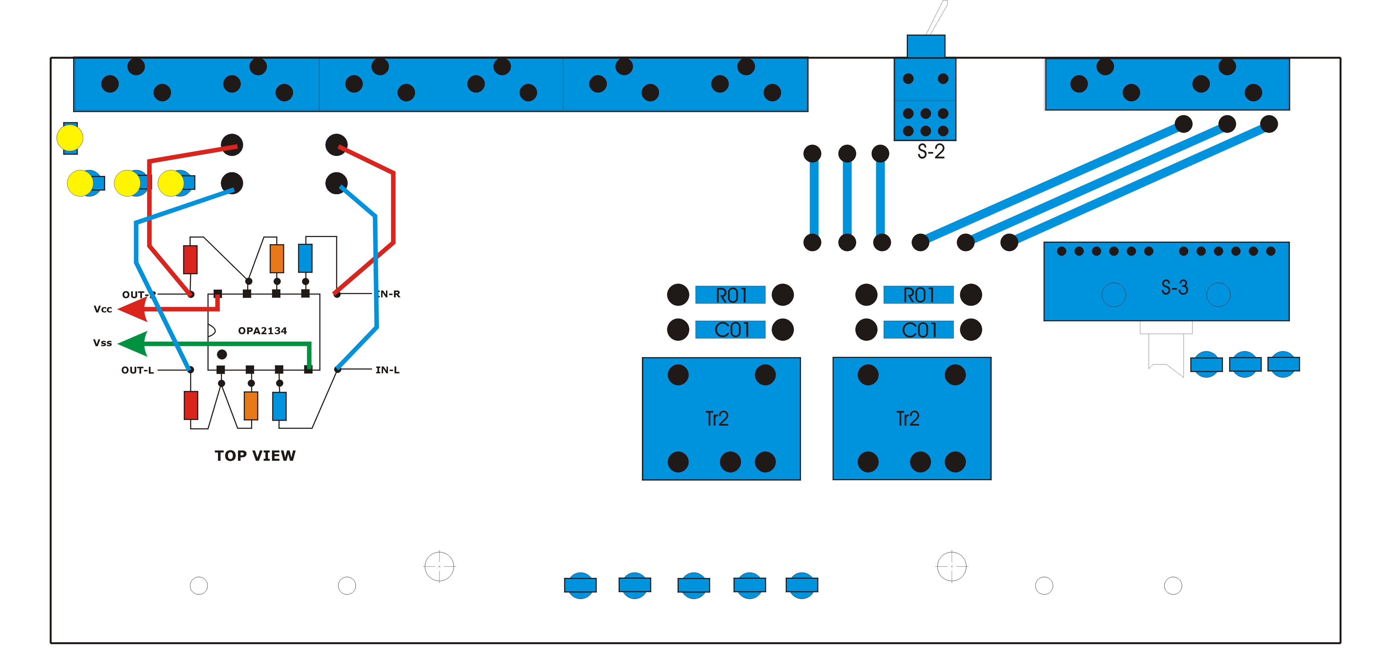
figure 6: connections to the MCML05 input PCB
(remove the two R41 = 1 kOhm resistors and use their soldering islands to connect to the buffer PCB)
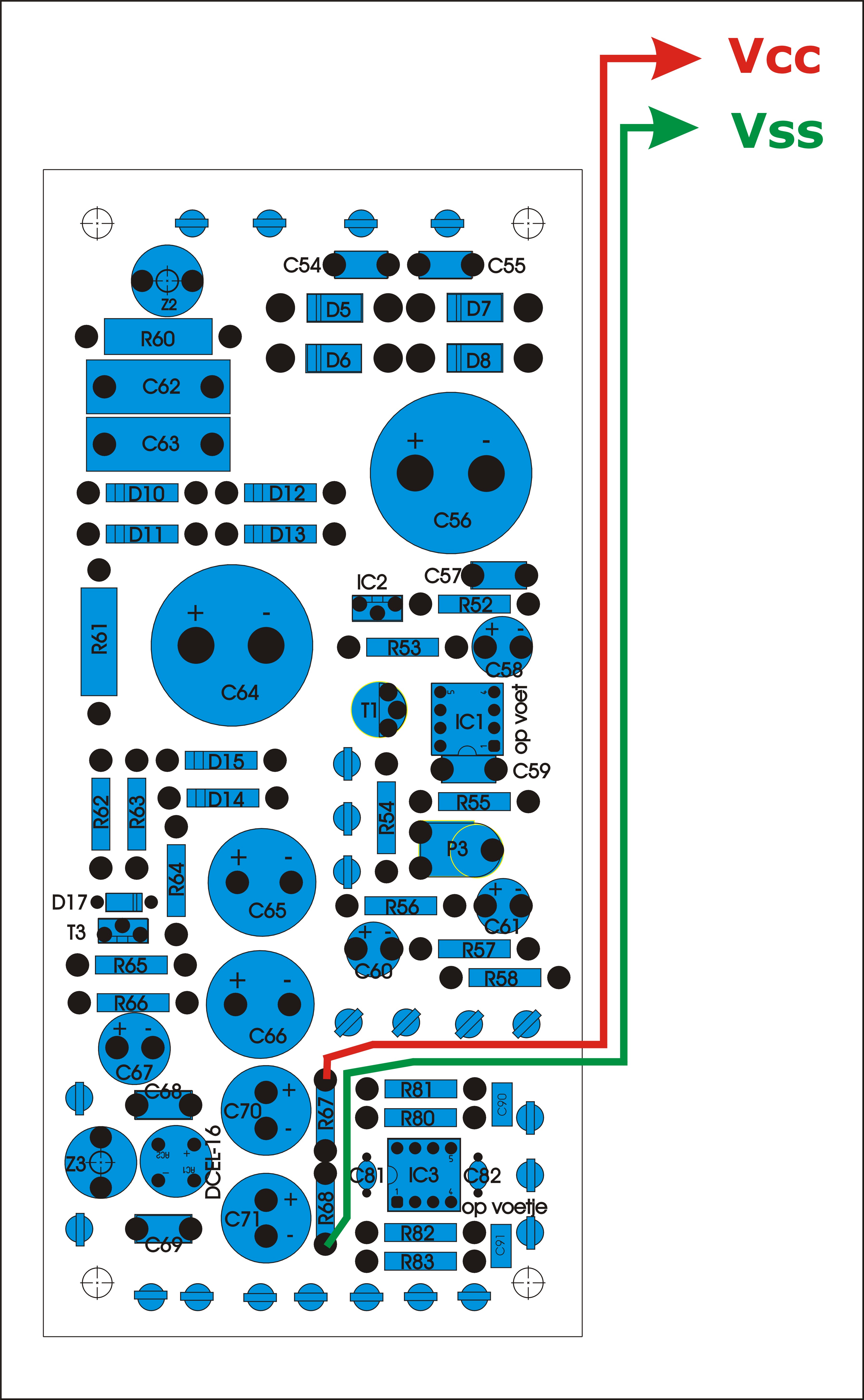
figure 7: how to connect Vcc and Vss
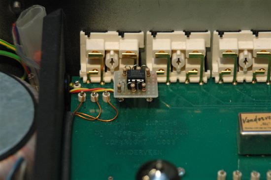
photo-3: the modification replaces the two R41 resistors
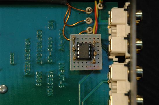
photo-4: the modification seen from the top
Explaining the new circuit
The input of the buffer goes through R1 to the plus-input of the operational amplifier. Its FET input impedance is extremely large, so, the signal sources hardly notice this buffer. R2 makes the amplification factor equal to unity and there is no phase inversion. The resistor R3 prevents large output currents in case the output is shorted to ground, while maintaining a low total output impedance. Is all that simple or is more going on?
Yes, more is going on, although it is hidden. Notice the low resistances of R1 and R2 for little resistor noise. R1 and R2 are almost equal, especially if you take into account the low output impedances of modern audio equipment. For lowest distortion the following condition should be met: R1+Zout = R2. In the manual of the OPA2134 and in the book of Douglas Self and in my own measurements it appears to be of the utmost importance to meet this condition. When met, the total harmonic distortion at least stays smaller than 0,005% at 20 KHz with 1 Vrms in a 10 kOhm load. Figure 8 shows the THD distortion of my computer soundcard measurement system, using ARTA and STEPS (www.fesb.hr/~mateljan/arta. The new buffer circuit actually distorts less, but I can not measure how much less. Then I should use a AP which measures down to 0,0005%, but I happen not to own that fantastic measuring beast.
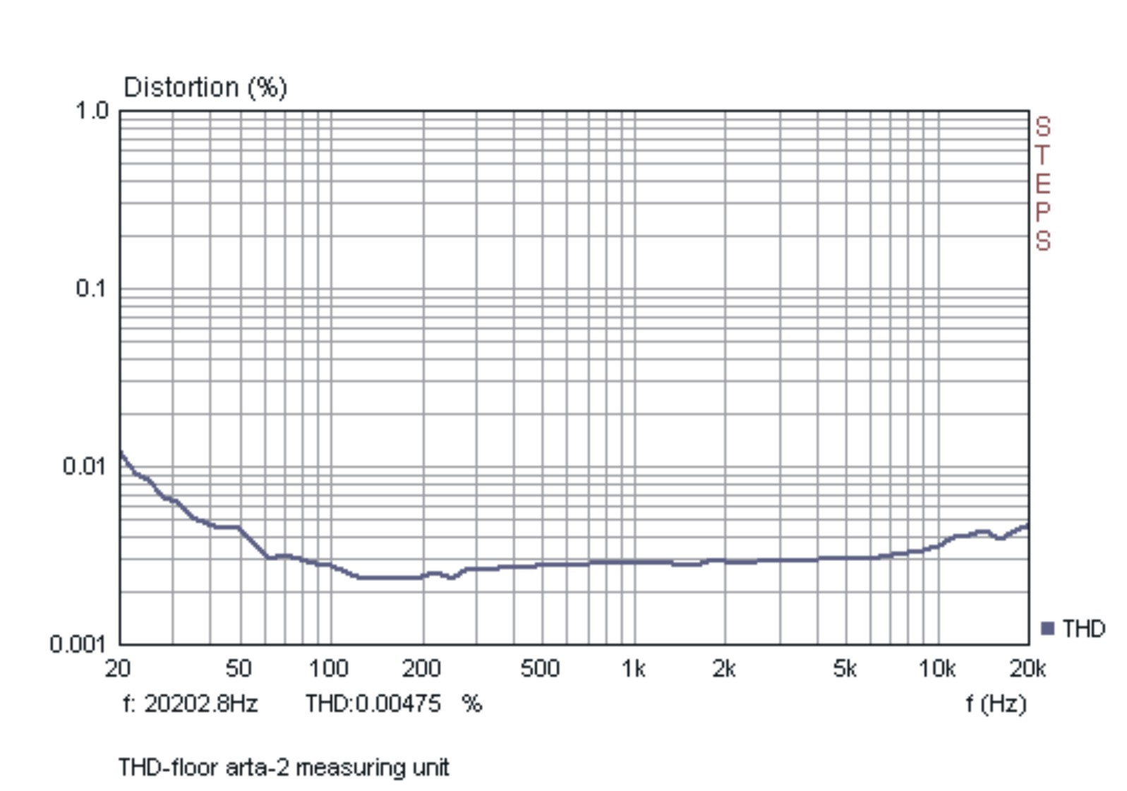
figure 8: residual distortion of my measuring sound card
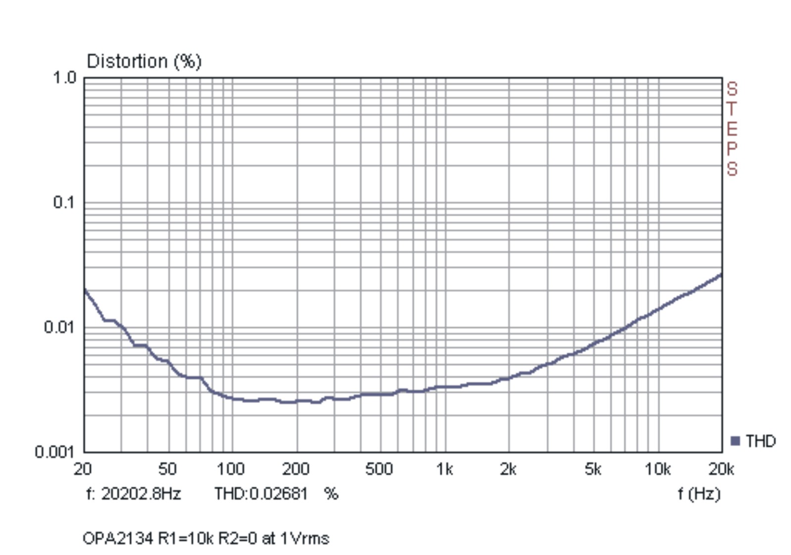
figure 9: THD in OPA2134 when R1+Zout is largely unequal to R2
Suppose you select with S-3 the turntable input. Then you have to deal with the output impedance of the valve RIAA pre amplifier. Its value is around 2 kOhm. Then R1+Zout = 3 kOhm, which is twice R2. Is the lowest distortion condition still met? Not totally, but THD stays below 0,005% and that is good enough for me; at this moment I can't do better. With the given resistances of R1 and R2 almost always the optimum is reached or you are close to it.
Final remark
As said, I leave the construction and implementation to you, it is such simple to do. Much success and in case of any remarks, please tell me by e-mail.
The Netherlands: September 27 2010
Nieuwe record buffer isoleert de MCML05 van zijn omgeving
MCM-MOD-3: Record buffer voor de MCML05. Deze modificatie voor de Vanderveen MCML05 buizenvoorversterker is helemaal gratis, je moet het helemaal zelf doen, er is geen printje beschikbaar, want de schakeling kan eenvoudig op een standaard gaatjesprint gemonteerd worden.

Waarom
Mijn voorversterker bezit een extra uitgang voor opname via een recorder. Deze uitgang wordt rechtstreeks afgekoppeld via een 1kOhm weerstand (R41) bij het moedercontact van de keuzeschakelaar; zie figuur 1.

figuur 1: schematuur van de recorderuitgang

foto-2: situatie voor de modificatie
De achtergrond van deze eenvoudige schakeling is dat de meeste recorders een hoge ingangsimpedantie hebben (omgeving van 100kOhm) en daardoor de signaalbronnen die op de MCML05 zijn aangesloten nauwelijks zullen belasten.
Ik moet nu toegeven dat ik hier een kleine misrekening heb begaan. Dat van die hoge impedantie klopt wel, maar ik heb geen rekening gehouden met het volgende verschijnsel.
Vroeger waren recorders uitgevoerd met buizen, en of het apparaat nu ingeschakeld stond of niet, de ingang was verbonden met het volledig vrijzwevende hoogohmige stuurrooster van de ingangsbuis. Dus er was nooit sprake van enige belasting van de op de MCML05 aangesloten bronnen.
Tegenwoordig zijn recorders en andere apparatuur uitgevoerd met IC's. Deze belasten de recorderuitgang van de MCML05 niet, zolang de recorders maar ingeschakeld staan. Zodra echter de recorder staat uitgeschakeld, is voor de IC's geen voedingsspanning meer aanwezig. De ingangen van de IC's zijn via beschermingdiodes verbonden met hun positieve en negatieve voedingslijnen. Daar staat bij een uitgeschakeld apparaat 0 Volt op, dus eigenlijk is de ingang van het IC via twee antiparallelle diodes via de voedingscondensatoren aan aarde verbonden. Figuren 2 en 3 laten overduidelijk zien wat er dan gebeurt.

figuur 2: beveiligingsdiodes begrenzen het ingangssignaal.

figuur 3: scoopbeeld van de begrenzing door de beveiligingsdiodes;
freq. = 400 Hz; vertical 0,5 V/div.
Het eindresultaat is dat de op de MCML05 aangesloten bron door deze diodes belast gaat worden, waardoor het geluid gaat vervormen. Dat kan natuurlijk nooit de bedoeling zijn.
Ik liep zelf tegen deze situatie aan omdat ik in mijn studio-opstelling de recorderuitgang had aangesloten op een mengpaneel voor verdere signaalbehandeling. Meestal staat dit mengpaneel uit en daarom moest ik steeds de recorderuitgang los nemen, wat onhandig is. Vandaar dat ik het plan opvatte om een eenvoudige buffer te maken die de recorderuitgang volledig scheidt van de bronnen die via de keuzeschakelaar van de MCML05 geselecteerd zijn. Die schakeling bespreek ik nu.
Altijd zijn er eisen
De eisen die ik aan de nieuwe recorderbuffer stel zijn behoorlijk veel. Er mogen geen condensatoren worden gebruikt, want die dingen "klinken" en dat wil ik niet. De schakeling moet extreem weinig vervormen en ruizen, een groot uitgangssignaal kunnen leveren en een meer dan ruim voldoende frequentiebereik bezitten. Ondertussen moet de ingangsimpedantie hoog zijn, want de buffer mag de bronnen niet belasten. De schakeling moet kortsluitvast zijn aan de uitgang, waarbij hiervan aan de ingang niks van gemerkt mag worden. De voeding van de schakeling mag de "aarde" niet belasten, want die is voor audiostromen vrijgehouden door de speciale printopbouw in de MCML05. De schakeling moet zonder enige wijziging aan de printen van de MCML05 kunnen worden toegevoegd. Hij mag de al aanwezige voeding nauwelijks belasten en hij mag nauwelijks gevoelig zijn voor de uitgangsimpedantie van de signaalbronnen (vooral deze laatste eis is zwaar).
Als mogelijke schakelingen heb ik overwogen: FET-buffer met uitgang op de source of een extra buis die als kathodevolger werkt. Het nadeel van de FET is dat deze teveel vervormt en de kathodevolger klinkt technisch en belast de voeding te zwaar. Dus die "oplossingen" heb ik niet gebruikt.
Ik heb uiteindelijk gekozen voor een opamp schakeling waarmee ik aan alle voorwaarden kon voldoen. Ik koos de OPA2134 als betere opvolger dan de al bekende TL072. Maar als ik Douglas Self mag geloven (en dat doe ik), had ik beter kunnen werken met de NE5534? Zie hoofdstuk 4 van "Small Signal Audio Design", by Douglas Self, ISBN 978-0-240-52177-0. Dit degelijke boek is een aanrader voor verdere studie en ontwikkeling.
De buffer schakeling
De uiteindelijke schakeling van de buffer staat in figuur 4, terwijl figuur 5 laat zien hoe je het op gaatjesprint kunt bouwen. Figuur 6 toont de aansluiting op de ingangsprint en figuur 7 laat zien waar je de Vcc en Vss voedingspanningen kunt aftakken op de voedingsprint. De daarop volgende foto's tonen hoe ik het gebouwd heb.

figuur 4: de bufferschakeling (1 kanaal getekend)

figuur 5: montage op gaatjesprint (stereo-versie)

figuur 6: aansluiting op de MCML05 ingangsprint
(verwijder de twee R41 = 1 kOhm weerstanden en gebruik hun soldeereilandjes om de bufferprint aan te sluiten)

figuur 7: aansluiting van de voeding

foto-3: de modificatie op de plek van 2 x R41

foto-4: bovenaanzicht van de modificatie
Waarom doe ik het zo?
De ingang van de buffer gaat via R1 naar de plus-ingang van de opamp. Deze is zeer hoogohmig, waardoor de signaalbron nagenoeg niet belast wordt. Via R2 wordt de versterkingsfactor van de opamp gelijk gemaakt aan 1 x terwijl er geen sprake is van fase-inversie. R3 aan de uitgang zorgt er voor dat er bij kortsluiting aan de uitgang niet te grote stromen gaan lopen. That's it, of is er ietsje meer aan de hand?
Ja, er is meer aan de hand. Wat opvalt is dat R1 en R2 laagohmig zijn voor weinig weerstandsruis. Tevens zijn R1 en R2 nagenoeg aan elkaar gelijk, zeker als je de uitgangsimpedantie van de meeste moderne signaalbronnen bij R1 optelt. De eis dat R1+Zuit = R2 is een extreem zware eis die er voor zorgt dat de vervorming van de opamp bij hoge frequenties gering blijft. Zowel Burr Brown als Douglas Self en ik (als resultaat van mijn metingen) onderstrepen deze eis voor THD vervormingen die kleiner blijven dan 0,005 % tot aan 20 kHz bij 1Vrms in 10 kOhm belasting. Figuur 8 toont de eigen vervorming van mijn geluidskaart die ik voor geijkte THD metingen via ARTA en STEPS gebruik (www.fesb.hr/~mateljan/arta). Op het punt van "ijking" hoop ik later terug te komen. Mijn eis was dat de vervorming in de recorder buffer zeker onder deze 0,005 % moet blijven en met de gemaakte keuze van R1 en R2 wordt hieraan voldaan.

figuur 8: residu vervorming van geluidskaart.

figuur 9: vervorming in OPA2134 als R1 sterk ongelijk is aan R2
Stel nu dat je de keuzeschakelaar van de MCML05 instelt op de platenspeler, dan heb je te maken met de uitgangsimpedantie van de buizen RIAA voorversterker (in de buurt van 2 kOhm). Dan geldt: R1-eff = 3 kOhm en R2 = 1k5; dus ze zijn ongelijk. Echter, dan wordt nog steeds voldaan aan de voorwaarde dat THD < 0,005 % at 20 kHz. De door mij gekozen waarden voor R1 en R2 zijn optimaal voor het handhaven van geringe THD onder nagenoeg iedere zinvolle uitgangsimpedantie van de signaalbron.
Naschrift
Zoals gezegd laat ik de zelfbouw helemaal aan de DIY-er over, zo eenvoudig is deze modificatie. Veel plezier ermee en als er opmerkingen zijn, dan hoor ik het wel via mijn e-mail.
The Netherlands: 27-9-2010
